String Accordion
Skip other details (including permanent urls, DOI, citation information)

: This work is licensed under a Creative Commons Attribution-NonCommercial-NoDerivatives 4.0 International License. Please contact [email protected] to use this work in a way not covered by the license.
For more information, read Michigan Publishing's access and usage policy.
Introduction
I make digital musical instruments. I find electronics sensors, hook them up to credit-card-sized computers, and write software to create sounds that react to the sensors. I like to put all these components in enclosures made of cheap ¼-inch plywood. I’m lucky to have access to a laser cutter machine, which allows me to use computer-aided design (CAD) software to cut precise designs into wood with lasers.
It’s difficult to make a digital musical instrument (DMI) feel like a real instrument. Because the form of a DMI does not determine the sound that comes out of the computer, creating an “instrumental feeling” (whatever that means) is an important aspect of the instrument. Most instruments are ergonomically designed, and I wish to capture that feeling in the instruments I build and perform with. I want an instrument to feel good in my hands. Plywood doesn’t usually feel good in my hands.
Why plywood? Because it is a cheap and relatively strong material that can be easily cut by a laser cutter. A laser cutter is exactly what it sounds like: a machine that cuts things with a laser. I can insert flat materials (like plywood) into the machine, upload a CAD file, and with the push of a button, the laser cutter guides a laser to accurately and precisely cut whatever I designed. The laser cutter I have the pleasure of using is an Epilog Laser Helix, which allows me to cut pieces up to 24″ × 18″ × ¼″.
The first instrument I built had an enclosure that was literally a box with holes in it. I put a guitar strap on it and called it good enough. By the time I was looking to improve the instrument, I had done some research into using plywood to make non-box-shaped objects. I stumbled upon a technique called “kerf bending.”
A kerf is a slit made by cutting. If you can cut a certain pattern into plywood (perhaps with a laser), it is possible to bend thin plywood without breaking it. I use this technique to build enclosures that fit the curve of a palm, because a handheld box doesn’t feel much like an instrument to me.
The most basic laser kerf pattern looks like this (from Instructables):
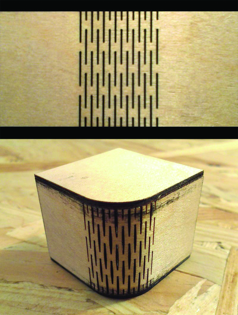
As shown above, cutting this pattern of staggered lines into the plywood relaxes it enough to bend a corner without breaking. I used this exact pattern in the second iteration of the instrument I mentioned earlier. That instrument is called the String Accordion, and it looks like this:

The String Accordion uses retractable string mechanisms (recycled from GameTrak video game controllers) as sensors for an instrumental interaction. The first iteration was housed in a box, the second iteration in a rounded triangular cylinder, and I’m currently working on a third iteration as part of my master’s thesis (Media Arts MA) at the University of Michigan.
While this article details my process for making a DMI enclosure using lasers and plywood, the larger picture is my dream to make a DMI that I actually like and want to play. I’m trying to build something that sounds and feels right to me (whatever that means). My previous attempts have left me unsatisfied on all fronts: the sound, the interaction, the feeling, the look. I feel like sometimes get a hint of one element that seems right, but the combination has been far from right so far.
This instrument building (and performing) process is a major component of my master’s thesis. The research community dedicated to DMIs is very good at using the latest technology to make new instruments, but few people actually engage with the instruments as part of their artistic practice. I believe that when the instrument is first built, the research has only just begun: I am interested in how DMIs are used and how their use may inform how DMIs are made. Perhaps more important, I’m interested in how they can be iterated on and what that means for musical practice with DMIs.
This article will now shift into a journal entry format, sharing my perspective on the process of creating the enclosure for my next iteration of the String Accordion. I start with the idea of wanting a scaled-down version—one that fits in the hand rather than slung via guitar strap. I have an idea for a “two tacos” design, reducing the number of enclosure pieces to two (from three in the previous iteration).
January 22, 2017
At this point, I’ve made two physical prototypes for instrument enclosures.
Physical Prototype #1: Cut on January 17, 2017
The first prototype tested my “two tacos” design idea, employing laser kerf-bending techniques in plywood to make an enclosure with two bendable pieces. It nearly worked, confirming my design theory, but failed due to my error in forgetting to account for the material’s thickness; the pieces bent around each other, but the holding tabs were not lined up. I broke both pieces in half coaxing them to fit together.

I also tested engraving an intricate design into the surface of the instrument. I was hoping to line up an engraved design to appear continuous around the instrument. The laser cutter I used was able to make the designs clear. The engraved design did not line up how I had hoped in the CAD file, and if I decide to employ a similar design in a more finalized instrument, I’ll need to replace the design. My reason for including engraved designs is to help the DMI look more beautiful in a traditional instrumental sense.
Physical Prototype #2: Cut on January 18, 2017
I fixed my measurement errors in the previous CAD file. I started working on another engraving scheme but decided to save that for later, when I would have a more solidified prototype. I cut the updated CAD file, and it at least fit together. There was some awkward spacing in its three-dimensional form that is at least partially attributed to the use of a warped piece of plywood, but at least I had something to feel.
I knew I didn’t like the feeling almost immediately. The bend where the hand wraps around feels too large to comfortably employ finger dexterity in any useful way. The body feels too long and would probably be heavy with electronics in it. When holding it and gesturing in a way that feels natural (like playing an accordion), I knew that the current design would not facilitate that movement in a satisfying way.
While ultimately unhappy with this implementation, I still think the “two tacos” approach may still have merit. I’m now considering cutting bends with obtuse angles for better ergonomics. I’m also sketching out other possible enclosure shapes that may yield better results.
I’ve almost run out of good plywood at this point, so I need to get some more soon. I also need to come up with a couple more CAD files iterating on the “two tacos” method.


January 26, 2017
I have acquired a large sheet of ¼-inch luan plywood and cut it down into 24″ × 18″ pieces for use on the laser cutter.
Physical Prototype #3: Cut on January 25, 2017
I started by sketching out an inverse “two tacos” design. Instead of cutting a curve into the end, I decided to try cutting a curve on top so that the hand faces down when using the instrument. If this works, the resulting musical gestures would (theoretically) facilitate better control of the string in the x-y plane.

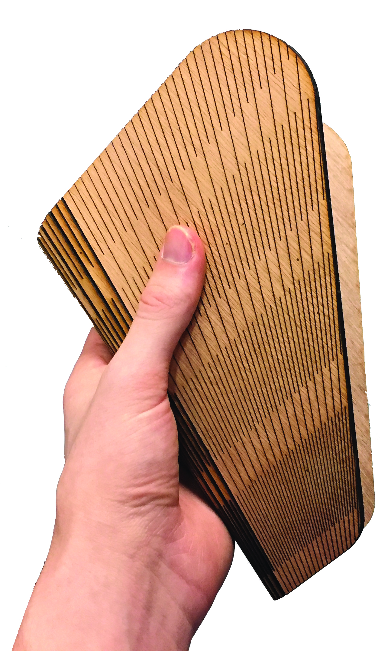
I also decided to try a new kerf-bending pattern. I saw this pattern online and thought it might make a smoother feeling curve. It also looks really cool, so I decided to make this prototype an aesthetic test as well as a structural test. I engraved the rest of the enclosure body such that the engraving lines seamlessly blend with the actual kerf lines. While the kerf cuts failed the structural stress test, I thought the aesthetic was nice. I am interested in exploring this aesthetic limitation (engraving design same as kerf cuts) in future iterations.
As stated above, this prototype did not hold up to structural stress tests. There seem to be pieces too large in the bending area to produce the dramatic curve I’m looking for.
I quickly cut a half-size version of the prototype to see if the pattern would work in small scale. While I did not completely break the main piece, I could tell there was no chance it would bend easily. The smaller piece broke when I poked it out of the wood sheet. This series of cuts did not produce what I was hoping for, but I learned some important things for the next prototypes.


January 29, 2017
Prototype shapes have shifted from rectangular to triangular to trapezoidal. I was inspired by the shape of the end-stop on a previous iteration of the string accordion, which featured a rounded triangle shape holding a kerf-bent tube together.
Physical Prototypes #4 and #5: Cut on January 27, 2017
I cut a triangle with kerfs through the middle of it to find out how it would look and feel in my hand. I cut straight kerf lines, and the shape reliably bent 180 degrees. I noticed how natural the form felt bending outward from my palm, and I figured I should attempt to facilitate that outward curve with the arrangement of the kerf cuts themselves.
I designed the same rounded triangle with a kerf pattern arranged such that one end had lines cut 1 mm apart and the other end had lines cut 4 mm apart. The gradual change facilitated a gentle outward curve I found pleasing to hold.

Physical Prototype #6: Cut on January 28, 2017
In order to fit the electronics in this instrument enclosure, I need more interior space than these current prototypes have. I designed a new enclosure in the shape of a parallelogram so the bent shape would look more like a right triangle, allowing more space on the wide end of the enclosure.

Not only was it very large, but it was also not structurally sound. Perhaps it is because I cut this piece against the grain of the plywood sheet. Perhaps it is because of the additional kerf lines I added in an attempt to make the bend more flexible. I was unfortunately unable to break this prototype in my own hands; it fell to the floor and broke before I had the chance to feel its flexibility.
I showed these prototypes to a friend, and they noticed how the design has some “useless space” at the point of the triangle would not fit much of anything inside. In order to increase space, they suggested making it taller and wider after cutting off the back end. I gave it a go, and the trapezoidal shape seemed promising.


January 30, 2017
Physical Prototype #7: Cut on January 29, 2017
This one works really nicely! The rounded trapezoid feels great in the hand, the outward curve yields a fair amount of space inside, and there is room for buttons where the fingers naturally rest. Upon handling this prototype for the first time, my original idea of holding the instrument away from the body (palms down) no longer makes sense; it feels much better to hold the enclosure like an open book (elbows in, palms up).
It would also do well to bend outward even more, though this poses a potential problem. If the kerf lines move outward at a sharper angle than they currently do, the bend will extend to where the fingers naturally grasp the enclosure. This is not good because I plan to have buttons where the fingers go, and while I’m sure I could figure out a way to do that, I would more comfortable putting buttons on flat surfaces rather than curved ones.
I decided to experiment by cutting nonlinear kerf patterns. While these examples were too small to curve 180 degrees like the larger prototypes, these experiments gave me hope that curved kerfs could be a viable method for maximizing outward bend and flat surface area.


February 2, 2017
Emboldened by the results of the curved kerf experiments, I decided to go all out and use the curved patterns in the trapezoidal prototype.
Physical Prototype #8: Cut February 1, 2017
At first I thought it worked. I was ambitious in the design, widening the curvature from 1–4 mm to 1–6 mm. The piece was able to fold completely, although it clearly felt strained in doing so. Before long, the prototype cracked down sides of the kerfing area.

I could tell something was wrong soon after handling the prototype. When bent, the wide ends were clearly straining to support the position I put it in. They jutted out like crooked teeth, which is something I had not seen before in my kerf-bending experience. My guess is that I’ll need to add an extra layer of kerf cuts to support the bend as it widens. I attempted that in physical prototype #6, so I’ll give that method another chance.
Physical Prototype #9: Cut February 1, 2017
In all my previous iterations, I’ve designed the kerf cuts using horizontal bands as guides. I thought about using curved bands to accompany the curved cuts just to see if it might work.
It failed immediately.
I used concentric circles at the same bandwidth as the horizontal bands in previous prototypes. I should have known how it would fail spectacularly, especially in basing the smallest circle where the larger-spaced kerfs are.

Perhaps this would work if the circular bands originated from the opposite side of the design. That would at least make more sense. I wonder if circular bands would help strengthen the curved kerf design; I’ve noticed that for the increased outward curve and flat space, these new prototypes are weaker than prototype #7 (which is still intact as of today).

February 9, 2017
It’s been a week of what has felt like constant failure with these prototypes. I’ve certainly been spinning my wheels, but a new design is showing some potential.


Physical Prototype #10: Cut February 2, 2017
This is the first iteration of the design with a kerf pattern that gets denser as the lines get farther apart. I measured previously successful kerf-bent pieces and found that approximately 3–4 mm is the distance between kerf lines that have been successful in previous projects. My ideal curve requires kerf lines that surpass the 4 mm mark, so I figured I would need to bisect the major kerf lines in order to achieve the bend I’m looking for.
I tried it and found out that having supporting kerf lines that bisect the major lines won’t solve the problem by itself. This design failed mostly in part to the high-density pattern weakening the wood so much that it fell apart with effort. I was unable to measure the angle of the bend because it broke so quickly.
Physical Prototype #11: Cut February 4, 2017
I decided to keep the same idea from prototype #10 but reintroduce the kerf pattern to the support lines as well as the major ones. I experimented with proportionally shortening the kerf pattern as a way to keep strength in the denser regions.

This, too, did not work. While the inside was much stronger, it became too strong and did not want to bend at all. The first stress test saw a crack up the side of the bending section of the piece.
With the kerf section broken away from the “wings,” it could be tested on its own. While it bent fairly well, I still got the “crooked teeth” effect at the end. This effect is problematic because when I make a piece to hold this bending piece together, I need a (at least) relatively smooth curve for the supporting piece to rest against. Without that, the enclosure won’t fit together at all.


Physical Prototype #12: Cut February 6, 2017
I took the weekend to go back to the drawing board. Something clearly isn’t working: Is it the curved kerfs? The spacing between the kerfs? Me trying to make wood bend in a way it simply cannot (in this small scale at least)? I talked with a few people who urged me to look at reshaping the design rather than attempt to make the shape solely through kerf-bending patterns.
I decided to try a design that had the curve built into it. This idea would potentially allow me to use a one-dimensional bend to get a deep curve. In my previous experiments (around the time of prototype #7), I worked on a double-parabolic pattern that would theoretically work just like a traditional parallel pattern. However, my implementation failed.
The bent section, while separated from the wings, curves in a satisfying way. This design is able to sustain a pretty large curve with minimal crookedness at the ends. With some time, I would be able to make this design work.
However, instead of figuring out how to make that specific shape work, I decided to meld this design with that of the previous trapezoidal prototypes.


Physical Prototype #13: Cut February 6, 2017
During the redesign process, I realized that I was altering the basic kerf pattern by bisecting the wider ends. I realized this might be the reason for the crookedness of the ends, and I decided to retry some previous designs with the original kerf pattern.
It didn’t work. It wasn’t flexible enough and broke near the wide end of the pattern. The pattern was not dense enough near the bottom.


Physical Prototype #14: Cut February 6, 2017
This prototype was the melding of the trapezoidal and butterfly designs and would theoretically work if it had a denser pattern near the bottom. This one simply wasn’t flexible enough.

Physical Prototype #15: Cut February 6, 2017
Tried the same thing as prototype #13 but with a denser pattern and wider angle. It was unable to hold together, but the ends curved in a much smoother way. The bent area was also plenty flexible but became separated where they connected to the sides of the trapezoid. My guess is that the cuts were too long or that the curves somehow reduce the integrity of the piece.


Physical Prototypes #16, #17, and #18: Cut February 8, 2017
At this point, I am concerned with making a piece that will fit into these kinds of designs. Instead of forging ahead with brute force as I have been for most of this process, maybe it’s time to think smarter and go for quality over quantity.
The reason for making these designs is to make wood curve out at a specific angle. I’m not sure what angle feels right yet, but at some point, I need to make an end piece that can turn these initial physical prototype shapes into enclosures. That means I’ll need to know the natural curve of a kerf-bent region. This is important because if the angles of the pieces aren’t lined up, I won’t have a square edge to keep everything together. This concept is illustrated in my journal sketches below.

I decided to redesign prototype #7, which has proven a reliable benchmark, such that the desired natural curving angle is built into the design itself. I have previously been “winging it,” measuring the curving angle only after the piece is cut. This time, I was able to achieve a twenty-degree bend (prototype #16) and almost a forty-five-degree bend (prototype #17).
I was unable to get a picture of prototype #18 at the time of writing this entry. I was able to get an unbroken forty-five-degree bend with some slight alterations to prototype #17. This precision will be extremely helpful in designing an end piece to complete the enclosure.


Reflections and Future Work
While this article chronicles a nearly monthlong process in developing an enclosure for my instrument, it is worth pointing out that this is a creative process on only one aspect of the instrument and that the physical form will likely change as I work on electronics and sound. This process was guided by touch, in how the instrument will feel. However, an arguably more important aspect of an instrument’s design is its sound at this point of the process.
Sound is abstracted and is not limited by the form of a DMI. Since the sound is programmed and generated by a computer, DMI makers do not need to think so much about how form will affect the sonic identity of the instrument. This means it is rather difficult to create an instrument that looks like it would make the sound that will eventually emanate from it.
Engaging in a process like I have does not help; as pointed out by my thesis committee, it would be a better idea to engage in a prototyping process with form, interaction, and sound all in play. The process I’ve followed in the past month certainly helps and shouldn’t be abandoned, but it relates only to form of the instrument—not so much its function. An instrument that looks nice doesn’t mean much when it doesn’t sound very good or isn’t usable.
As I mentioned in the introduction, I’m working toward an instrument that sounds, interacts, feels, and looks right. What I’ve learned from this month-long process, and from my thesis committee’s insight, is that these elements all inform one another. To focus on one element in isolation is a mistake, and I made a big mistake by focusing so narrowly on feel (and look) of the instrument. I got bogged down by my obsession with form.
It’s easy to look at this time as “wasted,” but that view only holds within the scope of this master’s thesis timeline. Yes, it would’ve been more efficient to engage in a more holistic instrument prototyping process given my dwindling time left to complete a thesis, but this experimentation also serves the bigger picture. By no means will the String Accordion be finished with the conclusion of my master’s thesis; these experiments, and the skills built through engaging in the process, are critical to the larger arc of the String Accordion’s evolution. That said, now is the time to step away from the idea of perfect form and pursue imperfect but combined form and function.
I hope this documentation of my experimentation is useful to anyone with access to a laser cutter interested in bending wood in very particular and curved shapes. My work here is far from done, but perhaps it will speed up the process for anyone new to laser kerf-bending techniques.
http://www.deferredprocrastination.co.uk/blog/2011/laser-cut-lattice-living-hinges/
http://www.deferredprocrastination.co.uk/blog/2012/lattice-hinge-design-choosing-torsional-stress/
http://www.instructables.com/id/Curved-laser-bent-wood/

